Geotab - GO Device Troubleshooting
Written By Philip Stanoev
This comprehensive troubleshooting guide provides systematic diagnostic procedures for resolving GO device communication and operational issues. The guide covers LED status verification, connection inspection, reset procedures, and electrical testing to identify and resolve common device problems through methodical troubleshooting steps.
Just installed and not showing yet?
A new GO device does not start reporting the moment it is plugged in. It activates the first time it connects to the network, and that normally needs the vehicle to be driven after installation. Until then the device can already be assigned to your database but show no location or trips.
Check the device is fully plugged in and secured so it cannot move or work loose.
Start the vehicle and drive it outdoors for about 10–15 minutes.
Check the map again after the drive. Activation starts automatically once the device connects for the first time.
If the device still does not appear, check which indicator lights are on (see Installation Testing Verification below), make sure no metal objects near the device are blocking its signal, then continue with Step One.
If you contact Support, include a photo of the serial number label on the device.
Step One: GO Device LED Status Verification
Initial Device Assessment Process
Device Location: Locate the GO device installed in your vehicle for physical inspection and testing. Important Note: Accessing the GO device may require dash panel removal and cable tie cutting. Do not cut the cable tie securing the GO device to the T-harness at this stage.
Engine Activation: Start the vehicle engine for system power activation.
Engine Runtime: Run the engine for approximately 60 seconds to ensure complete system initialization.
Communication Testing: With engine running, visit install.geotab.com for device communication verification.
Serial Number Entry: In the Device Serial No field, enter the serial number located on the GO device for communication testing.
Communication Status Assessment:
If result shows "Device Not Communicating," proceed to Step Two for connection verification
If result shows "Device Communicating" but Blue LED does not activate, refer to Troubleshooting the Blue LED section
LED Status Verification: Check GO device LED status for operational indicators.
Alternative Testing Options:
If no LEDs activate, connect spare device if available for comparison testing
If spare device unavailable, test current device in another working vehicle to determine device functionality
Continue troubleshooting in original vehicle by proceeding to Step Two
Blue LED Troubleshooting Reference: https://support.geotab.com/mygeotab/doc/device-trouble-guide#h.wr4hhbnt3725
Step Two: Connection Verification
Physical Connection Assessment
T-harness Connection Verification: Check secure connection between T-harness and GO device ensuring firm cable tie fastening for proper electrical contact. Direct Connection Note: In some installations, device connects directly to vehicle diagnostic connector requiring physical verification of complete plug insertion.
Vehicle Connector Verification: If T-harness securely connects to GO device, verify secure connection between T-harness and vehicle diagnostic connector.
Problem Persistence: If connections remain secure and problem persists, proceed to Step Three for reset procedures.
Step Three: Hard Reset Procedure
Complete System Reset Process
Engine Shutdown: Turn engine off completely for system power down.
Connection Disconnection: Unplug T-harness from both GO device and vehicle diagnostic connector for complete electrical isolation.
Pin Inspection: Examine pins on T-harness and diagnostic connector for physical damage or corrosion.
Harness Replacement: If T-harness pins show damage, complete harness replacement required for proper operation.
Reconnection Process: If no pin damage detected, reconnect T-harness to GO device and vehicle diagnostic connector.
Startup Verification: Start engine and listen for six quick beeps indicating successful startup sequence.
LED Status Recheck: Verify GO device LED status after reset procedure completion.
Continued Troubleshooting: If LEDs remain inactive, proceed to Step Four for electrical testing.
Step Four: Electrical Testing with Multimeter
Power and Ground Verification
Engine Shutdown: Turn engine off for safe electrical testing procedures.
T-harness Disconnection: Unplug T-harness from vehicle diagnostic connector for pin access.
Engine Restart: Start engine for electrical system activation during testing.
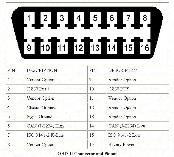
Multimeter Testing: Use multimeter to check pins on vehicle diagnostic connector according to connector type:
16-Pin Diagnostic Connector
|  |
9-Pin Diagnostic Connector
|  |
6-Pin Diagnostic Connector
|  |
Power Verification: If no power detected on power pin, consult manufacturer instruction manual for fuse location and replacement procedures.
Equipment Replacement: If troubleshooting steps fail to resolve issue, contact partner for GO device and T-harness replacement as equipment failure likely cause.
Warning Lights or Fault Codes That Appear Only When the GO Device Is Connected
If the vehicle throws engine or transmission warning lights, sweeping or erratic gauges, or communication fault codes while the GO device is plugged in, and those symptoms disappear when the device is unplugged, the device is not failing. The plug/unplug test is the discriminator: symptoms that follow the connection point at the device interacting with the vehicle data bus, not at a device or power fault. Steps One through Four above will not find this. The device will usually report normally and pass every LED, reset and multimeter check.
Confirm It Is Bus Interaction, Not a Vehicle Fault
With the engine off, unplug the T-harness from the vehicle diagnostic connector.
Start the engine and let it run. Note which warning lights and gauge behaviours are present with the device disconnected.
Shut the engine off, reconnect the T-harness, and repeat the observation.
If the symptoms are present only in step 3, treat this as bus interaction and continue below. If they are present in both, the fault is in the vehicle and is not caused by the GO device. Refer it to the vehicle's service provider.
Do not run this section's procedure before checking the T-harness and diagnostic-connector pins for damage or corrosion. That inspection is covered in Step Three above, and damaged pins can produce similar symptoms.
Correct the Vehicle Model File
The vehicle model file tells the device how to communicate with that specific vehicle. An incorrect or missing model file is the usual cause of bus interference, and correcting it is the fix that preserves full data reporting.
Confirm the exact year, make, model and engine configuration of the vehicle.
Verify the model file currently applied to the device against that vehicle.
If the model file is wrong or missing, request the correct one from support.
After the corrected model file is applied, run the plug/unplug comparison again to confirm the symptoms are gone.
If the Model File Cannot Be Corrected
Hardwiring the device removes the bus connection and therefore removes the interference. This is a trade-off, not a free fix:
OBD (diagnostic connector) installation reports fuel, turn signal, odometer and speed.
Hardwired installation reports only power, ground and ignition. Fuel, turn signal, odometer and speed data are lost for that vehicle.
Confirm with the account owner that the reduced data set is acceptable before converting an installation to hardwired.
After the Symptoms Are Resolved
Warning lights already stored by the vehicle may remain illuminated for a time after the cause is removed. Stored fault codes do not need to be cleared; they clear on their own.
If the symptoms persist with a confirmed-correct model file and undamaged pins, contact your partner for GO device and T-harness replacement, as covered under Step Four.
Post-Troubleshooting Procedures
Successful Resolution Follow-Up
Connection Security: After successful troubleshooting resolution, resecure all connections using cable ties if previously cut during diagnostic procedures.
Device Mounting: Mount device to secure, solid vehicle location with GPS antenna facing skyward if device was dismounted during troubleshooting process.

Installation Testing Verification
Prerequisites: Ensure GO device serial number and vehicle information availability before beginning verification test.
LED Status Verification Process
Engine Activation: Start vehicle engine for system power activation.
LED Status Confirmation: Verify GO device LED operational status:
Red LED: Ignition (Engine ON) detection confirmation
Green LED: Cellular network connection establishment
Blue LED: GPS network connection verification
LED Troubleshooting Procedures
Green LED Issues: If Green LED does not activate, position vehicle in area with strong cellular coverage for network connectivity improvement.
Blue LED Issues: For previously installed GO devices, Blue LED should activate automatically. If inactive, ensure vehicle has clear sky visibility. Drive vehicle if necessary to activate Blue LED functionality.
Installation Finalization
Installation Verification: Verify GO device installation completion using install.geotab.com for final system confirmation.
Vehicle Restoration: Reattach any removed dash panels and return vehicle to original operational position for continued service.
Technical Considerations
Safety Procedures
Electrical Testing: Exercise caution during multimeter testing procedures to prevent electrical system damage or personal injury during diagnostic procedures.
System Requirements
Communication Testing: Ensure stable internet connection when using install.geotab.com for device communication verification and system testing procedures.
The GO device troubleshooting guide provides systematic diagnostic procedures for identifying and resolving common device operational issues through methodical testing and verification steps for optimal device performance and functionality.
Still need help? Ask the team