ZenCAM PLUS Installation Guide
Written By Support Team
📄 Download PDF Version: Attached Below 🢃
zencam-plus-installation-guide-10-6-2025.pdf
11.2 MB• Document
1. Introduction
Welcome to the ZenCAM PLUS Installation Guide. This guide is designed to help you through the installation and setup process of ZenCAM plus, whether you are a professional installer or a fleet manager, ensuring your camera system is installed correctly and optimally.
2. System Overview
ZenCAM PLUS can be installed with the following:
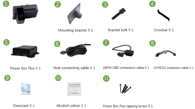
2.1 Diagnostics Box (included):
Can be hardwired (recommended) or installed through the OBD port.
Ideal for installations requiring vehicle diagnostics integration.
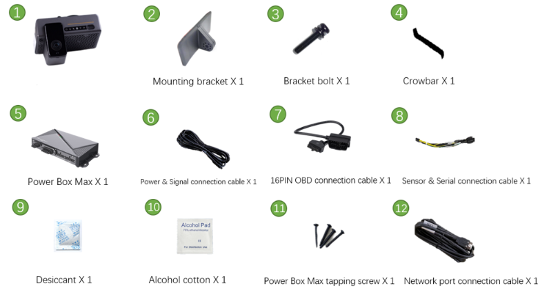
2.2 Power Box Max (not included with the ZenCAM Plus):
Allows expandability to six channels.
Can be hardwired (recommended) or powered through OBD port.
Perfect for complex setups requiring multiple camera channels.
3. Pre-Installation Checklist
3.1. Tools & Equipment
1 |  | Common screwdriver kit | Tighten screws, optional | 1pc |
2 |  | Crowbar | Pry up the vehicle panel | 1pc |
3 |  | Ties | Bundle cables | Prepare as needed |
4 |  | Dry cleaning cloth | Clean the dashboard | 1pc |
5 |  | Mobile phone/Pad | Install the Veyes App for video preview and parameter configuration. Download links
| 1pc |
6 |  | Steel tape | Measure the installation height of the forward-facing ADAS lens and assist the installation in other scenarios | 1pc |
7 |  | Mark pen | Mark lines for Dashcam installation | 1pc |
8 |  | Cutting nippers | Cut and strip wires | 1pc |
9 |  | Insulated rubber tape | Wrap wire ends | 1pc |
10 |  | Scissors | Cut insulated rubber tape or wire clip | 1pc |
11 |  | Multimeter | Locate vehicle power supply, measure the conduction of harness, and measure pulse signal | 1pc |
12 |  | Waterproof tape | Waterproof protection for outdoor wire connectors | 1pc |
13 | 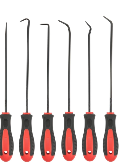 | Hole and Poke Tool | It is used to poke a wire to add external wire connections | 1 Set |
14 | 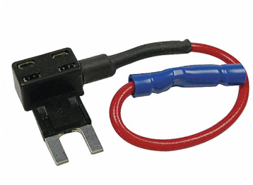 | Fuse Add a Circuit | Connections To add a extra fuse line on the current running electrical fuse | 2 per Camera |
15 | 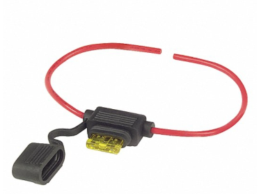 | Fuse Link | To add fuse for safety before any external connection | 2 Per Camera |
16 |  | Soldering Iron | It is used to solder the connection | 1 |
17 | 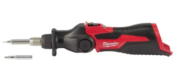 | Soldering Tool | Need to solder | 1 |
18 | 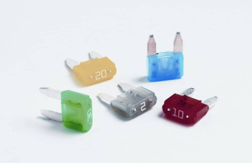 | Fuses | Use max 5 amp | As needed |
3.2. Safety Precautions
Ensure the vehicle is turned off and parked in a safe, stable environment.
The vehicle should be on a flat surface to prevent any movement during installation.
Wear protective gear as necessary (gloves, eyewear).
4. Installation Process
4.1 Installation of SIM Card and Memory Card
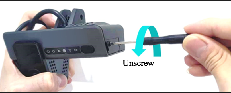
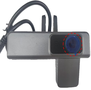
Take out the Dashcam (power-off), and use the Allen key in the kit to open the card slot panel on the right of the Dashcam by turning counterclockwise.
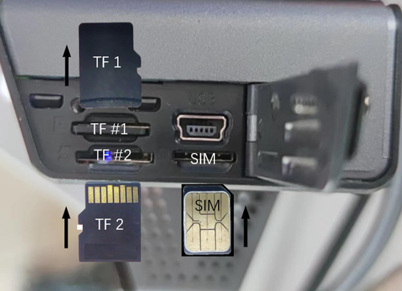
Install SIM card and Micro SD card as shown in the figure below (pay attention to the insertion direction of the cards).
Once you hear the click sound when pushing in the cards completely, it indicates that the cards are installed in the correct direction; if there is obvious friction resistance during installation, it indicates that the installation direction is wrong. Take out the cards in time to avoid any damage to the cards and the card holder.
If the Micro SD card and SIM card are too small to be pushed in the card slot completely by hand, you can put the card in the card slot and then push it in with the crowbar included in the package.
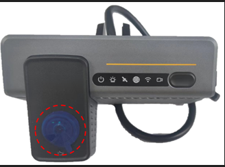
After installation of the SIM card and Micro SD card, remove the lens protection stickers on the front and rear lenses of the Dashcam, and tear off the protective film on the LED light on the front panel, as shown in the figure below.
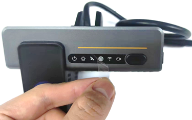
Installing SIM The Correct Way
4.2 Wiring and Power Connection
Hardwired (recommended method):
Run the cable through the vehicle’s headliner to the fuse box.
Ensure the power box is firmly mounted
Connect the respective wires to the fuse box
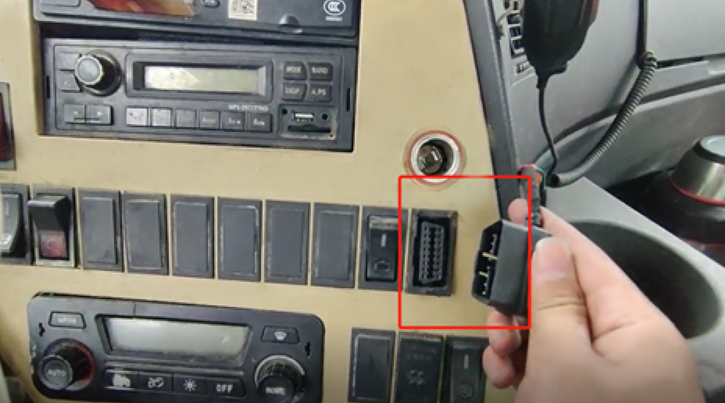
OBD :
Run the cable through the vehicle’s headliner to the OBD port
Ensure power box is firmly mounted
Connect the camera’s OBD connector to the vehicle’s OBD port.
Below is the Information on how to set up the wirings for different power boxes
4.2.1 Diagnostics Box
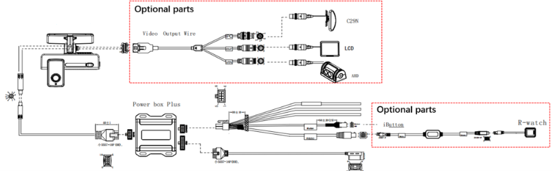
Connect the camera to the Host connecting cable and run the cable through the vehicle's headliner to either the OBD port or the fuse box based on the chosen installation method and ensure Power Box is firmly mounted
If you are using the OBD connection, then after running the cables next to the OBD port, connect the cables to the Power Box Plus, firmly mount the Power Box and then connect it to the 16PIN OBD connection cable and secure the connection
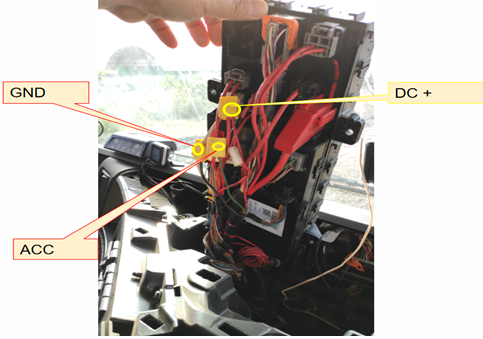
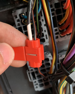
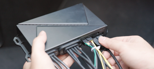
If you are hardwiring the connection (recommended), then after running the cables next to the Fuse Box, connect the cable to the Power Box Plus, firmly mount the Power Box and then connect it to the Hardwire connection cable and secure the connection to the fuse box as shown below
Red wire to constant power
Black wire to ground
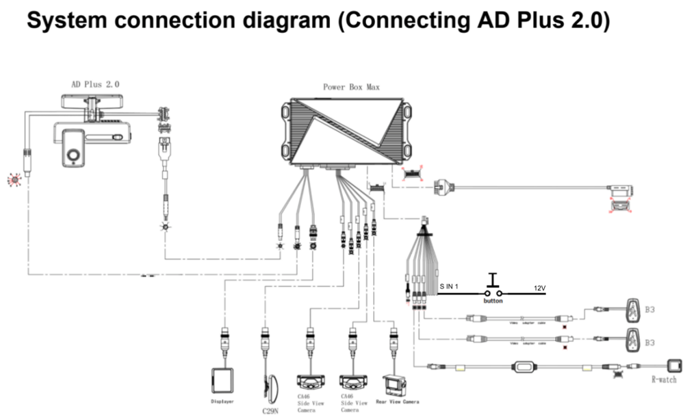
4.2.2 Power Box Max (required if solution has 3 or more auxiliary cameras)
Connect the camera to the Power & Signal Connection Cable and Network Port Connection Cable and run the cables through the vehicle's headliner to either the OBD port or the fuse box based on the preferred installation method and ensure Power Box Max is firmly mounted
If you are using the OBD connection, then after running the cables next to the OBD port, connect the cables to the Power Box Max, firmly mount the Power Box and then connect it to the 16PIN OBD connection cable and secure the connection
If you are hardwiring the connection (recommended), then after running the cables next to the Fuse Box, connect the cables to the Power Box Max, firmly mount the Power Box and then connect it to the Hardwire connection cable and secure the connection to the fuse box as shown below
Red wire to constant power
Orange wire to Ignition power
Black wire to ground
5. Camera Placement & Installation of Dashcam Bracket
5.1 Camera Placement
Identify the recommended installation location on the windshield.
Please refer to the below diagram to ensure correct placement, avoiding obstructions and without blocking driver view
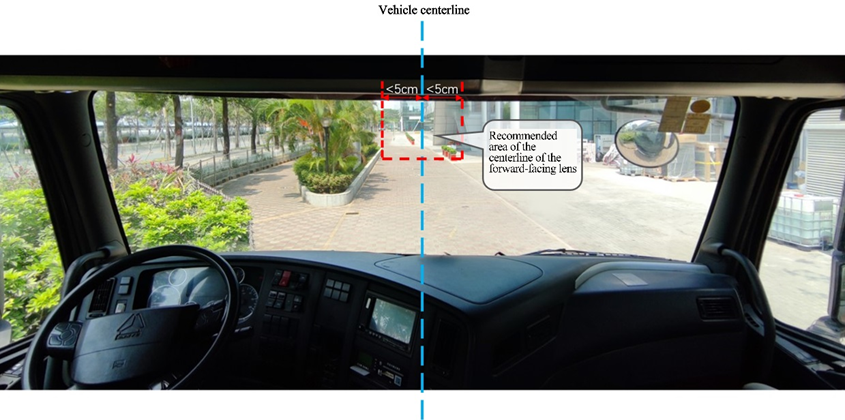
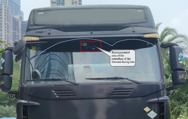
Park the vehicle on the horizontal ground, clean the interior and exterior of the glass in the target installation area with alcohol cotton to ensure that no dirt on the glass in this area will affect the angle of view of the lens for road condition monitoring, and ensure the glass is dry. Additionally, notice the curved lines above the red dotted line target recommended installation area in the picture above. The wiper blades of the vehicle will be cleaning the exterior of the glass, so ensure that the camera is installed in an area cleaned by the wiper blades.
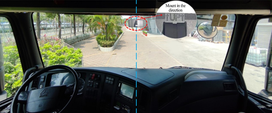
Tear off the 3M adhesive tape, install the bracket horizontally on the target installation area of the front windshield (the upper edge of the bracket should be parallel to the upper edge of the windshield) according to the direction indicated by the arrow on the bracket, and press the bracket for 10s to ensure that no air bubbles remain between the bracket and the glass.
Note: When installing the bracket, install the bracket according to the direction indicated on the bracket, so that the toothed side faces to the right.
5.2 Installation of Dashcam
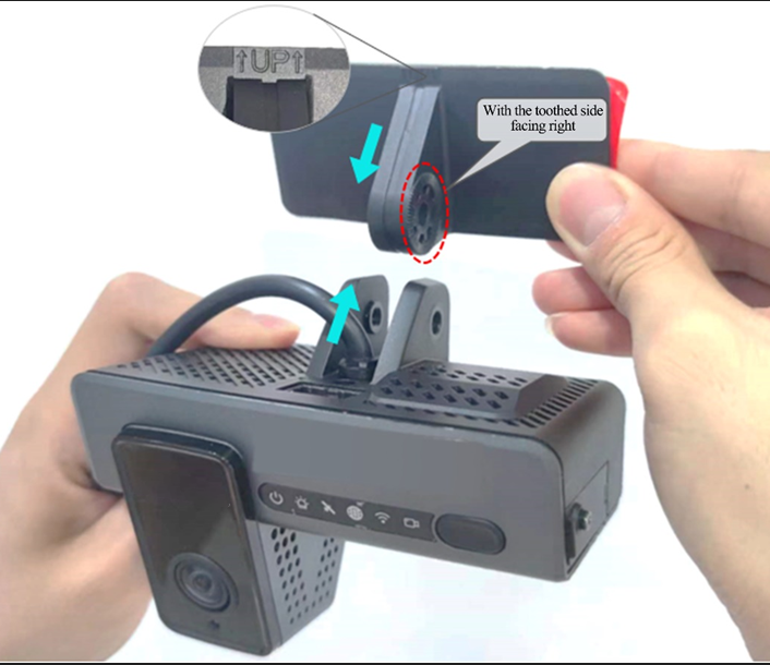
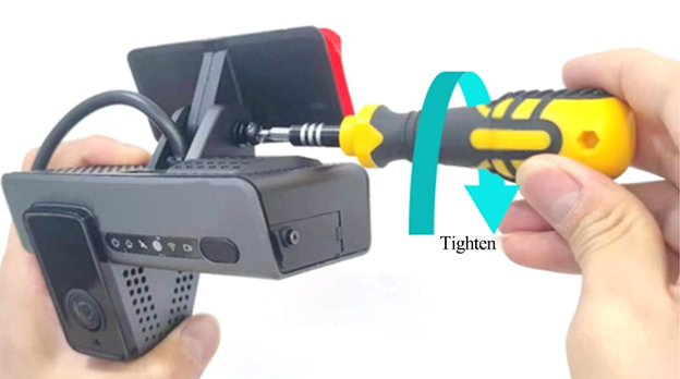
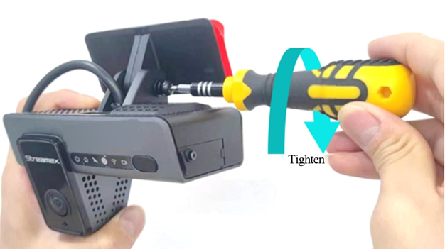
Connect the Dashcam to the bracket with the front side facing inward (with the teeth on the right side of the bracket engaged with those on the right inner side of the Dashcam), and tighten the bracket stud clockwise with a PH2 cross screwdriver enough so that it holds, but loose enough to adjust the viewing angle.
5.3 Angle Adjustment
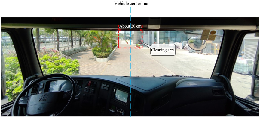
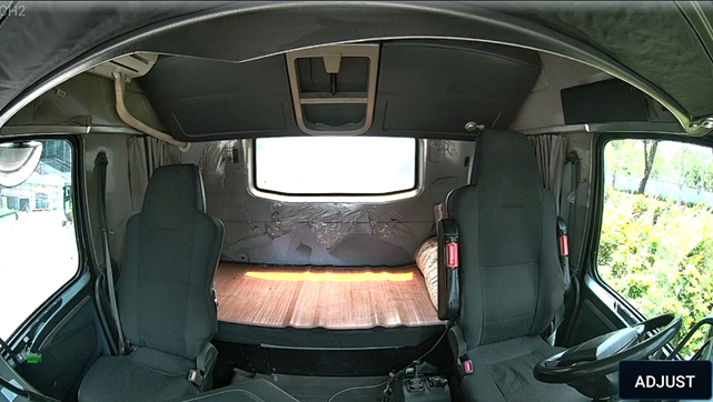
Before tightening the bracket stud to ensure that the angle of the Dashcam will not be changed easily, adjust the angle of the Dashcam tilting up or down until the following conditions are met:
The center of the cockpit shall be in the middle of the screen.
The cockpit screen shall be horizontal.
The vehicle steering wheel shall be shown at the lower left/right corner of the screen.
See below an example of the view of the cockpit after the Dashcam has been properly adjusted.
Use a screwdriver to fasten the bracket studs clockwise so that the Dashcam will not shake easily.
Note:
Make sure that the connection between the bracket and the Dashcam is fastened (the device is rigidly connected with the vehicle), so that the Dashcam will not shake easily. Otherwise, the GPS positioning will be inaccurate.
Only after the Dashcam is firmly connected with the vehicle can the device be powered on.
If the device is fixed and installed after power-on, it shall be powered on again before being tested or used.
6. Calibration and Configuration
6.1. ADAS Calibration Setup
This section applies to all power boxes
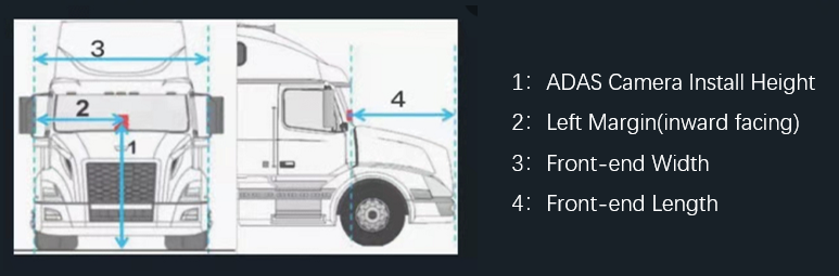
Measure the vertical height (accurate to cm/inch) from the ground to the lens for road condition monitoring of ZenCAM with a tower ruler or tape and take it as the ADAS lens installation height.
Measure the horizontal distance from the lens for road condition monitoring of ZenCAM to the outermost edge of the left tire (standing outside the vehicle and facing the left side of the front end) and take it as the left margin of the ADAS lens.
Measure the front end width (the distance between the outermost edges of the tires on both sides) and the front end length (the horizontal distance from the ADAS lens to the license plate). Refer to the figure below for the example of distance measurement.
Note: When the vertical height from the ground to the lens for road condition monitoring of ZenCAM is measured, read the height value after making sure that the tower ruler or tape is perpendicular to the ground.
After taking the measurement above, follow the steps below:
If you haven't already, download the Veyes app from the links below:
Power on the unit and wait for the camera WIFI LED to turn on
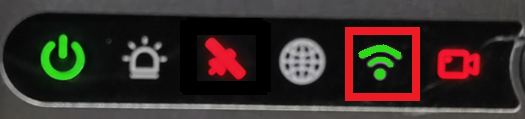
Connect to Wi-Fi. (Ensure connected to camera 003F or 00D2 or 00710).
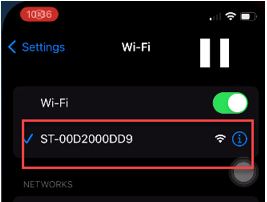
Launch Veyes application and ensure you are connected to the camera and enter the following credentials:
Username: admin
Password: For password contact our support at support@zenduit.com +1 (855) 936-3848 x 2
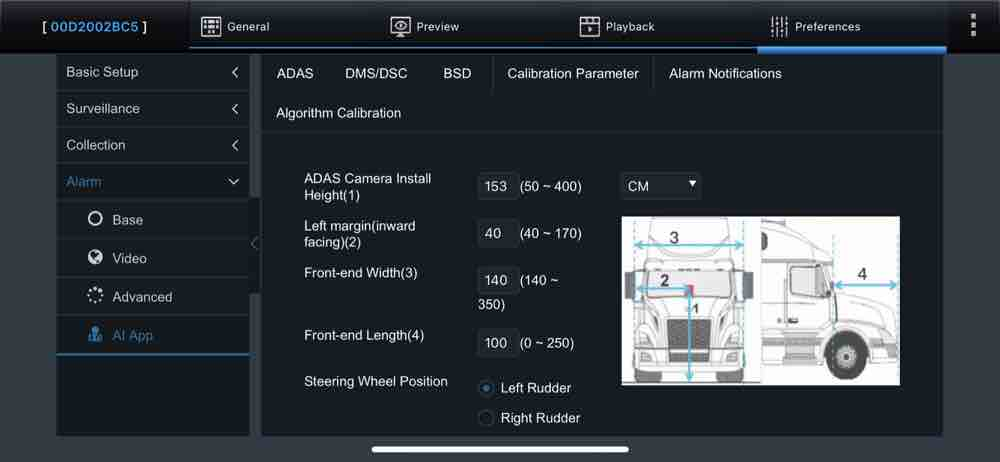
After the connection is completed, log in to the Veyes app and navigate to Preferences > Alarm > AI App > Calibration Parameter, the ADAS calibration height can be in cm or in inch. In the parameter input boxes, fill in the ADAS lens installation height, the left margin of the ADAS lens, and the front end width and front end length read in the previous step, respectively. Select left rudder or right rudder at Steering Wheel Position. The vehicle is a left rudder one if the driver's seat faces forward and the steering wheel is on the left side of the cockpit and a right rudder one if the steering wheel is on the right side of the cockpit. Tap Save after filling in the parameters and the steering wheel position
6.2 Diagnostic File Setup
This section applies only if Diagnostic Box and Power Box Max were installed using OBD connector
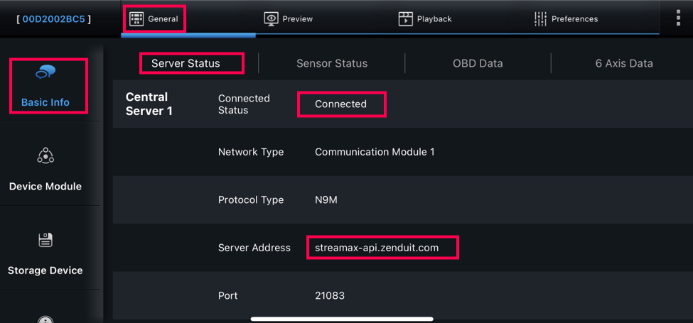
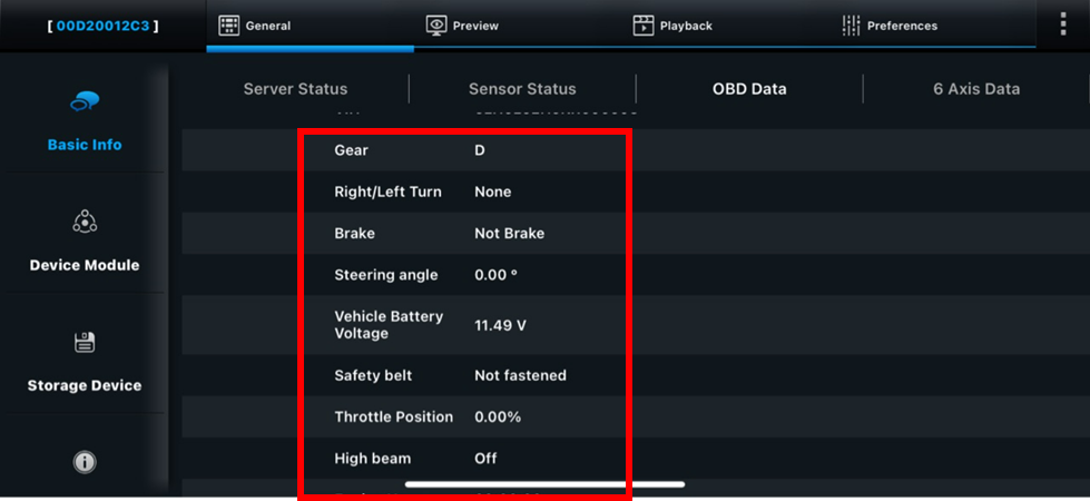
While connection is still established, navigate to General > Basic Info > Server Status and ensure that the server is connected
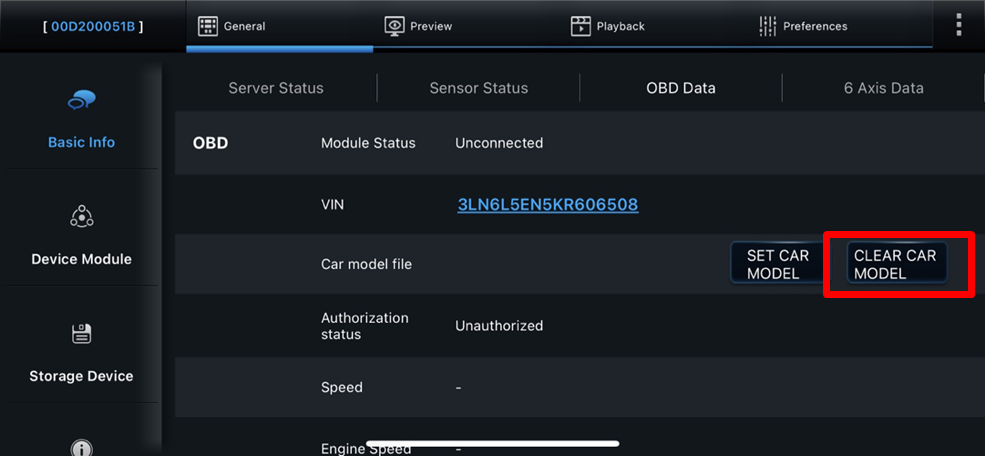
After ensuring the server is connected, navigate to the following Genera > Basic Info > OBD Data and enter the VIN of the camera
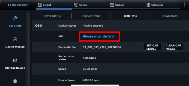
The system displays ‘invalid content!’ if the VIN content is incorrect.

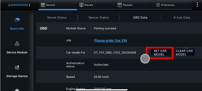
After inputting the VIN, click on SET CAR MODEL to enter the setting model interface.
Select the corresponding vehicle type according to the brand information of the vehicle
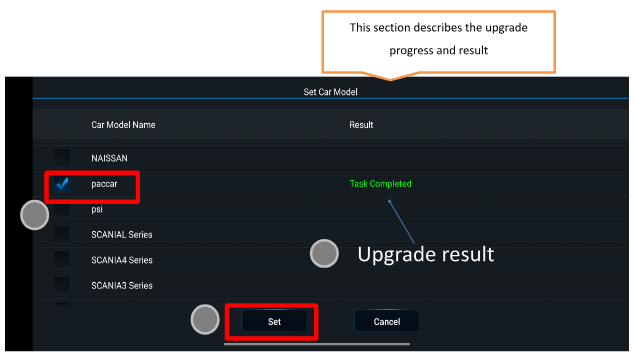
After selecting the corresponding model, click Set to upgrade the model file online and wait for the upgrade result of the model file
Result is the upgrade result display area, and the Task Completed indicates that the upgrade is successful. After the upgrade is successful, data verification and testing can begin
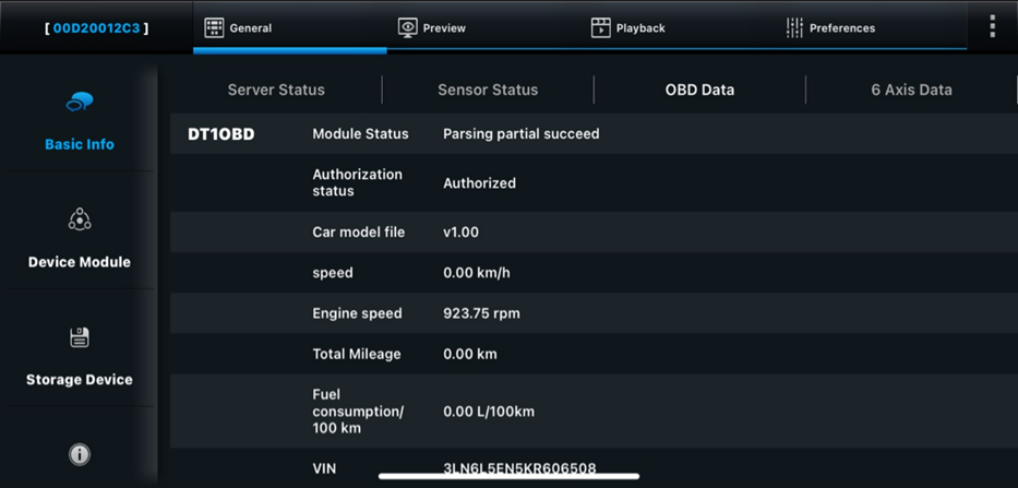
Ensure OBD data coming in the list below, some data points won’t be available as the car model do not support them
Note:
1. Please confirm whether the model is correct. An inconsistent model may cause faults on the vehicle instrument!
2. This product only supports original models, not modified vehicles. If instrument failure is caused by docking modified vehicles, please be responsible for all consequences!
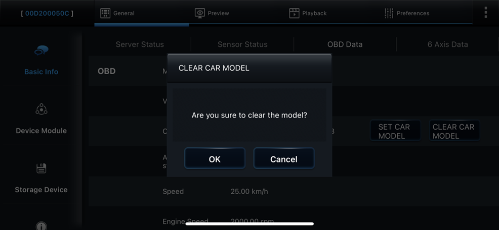
3. When replacing the vehicle, in order to ensure that the device will not send the agreement content of the previous vehicle, resulting in instrument failure, click 【CLEAR CAR MODEL】 before disassembly and assembly.
6.3 Power Box MAX Expandability Setup
This section applies only if Power Box Max is installed
Given that the camera is connected to Power Box Max, it is powered on and the Auxiliary cameras are connected as shown below.
You can connect up to four 4-pin Aux cameras OR three 4-pin Aux cameras and one 6-pin Aux camera
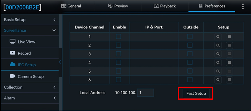
The camera and Power Box Max are connected by two cables, one is a power cable and the other is a LAN cable. Therefore, video data is transmitted through the LAN. Click fast setup in IPC Setup. Then the Fast Setup screen pops up, and shown the extern video channel:
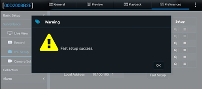
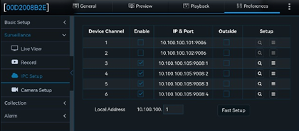
Click IPC Bind to complete the channel binding. The device prompts “fast setup success” and device channels Displays the channel IP address and port corresponding to Power Box Max
While on the Veyes app: Go to Preferences>Surveillance>IPC set up and click on Fast Setup as shown in the screenshot below:
Then the Fast Setup screen pops up, and shown the extern video channel:
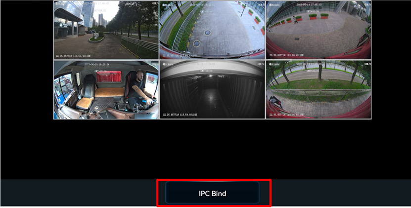
Click IPC Bind to complete the channel binding. The device prompts “fast setup success” and device channels Displays the channel IP address and port corresponding to Power Box Max.
6.4 Input Sensors Setup
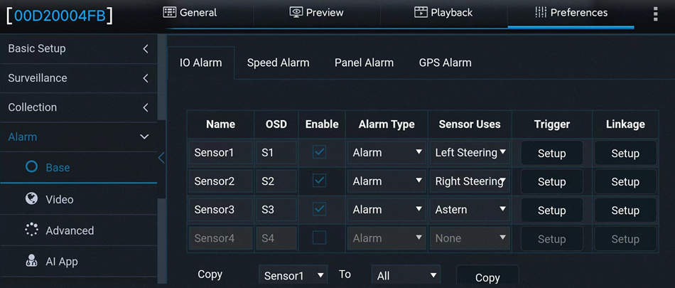
The device is equipped with a conventional power box and supports up to 10 inputs, including 4 IO inputs.
IO Alarm Screen Overview:
Serial Number:
Options include Sensor1, Sensor2, Sensor3, and Sensor (up to eight IO inputs are supported when using the UPS power box).
Name:
Sensor names can be customized or modified to suit specific requirements.
OSD (On-Screen Display):
Represents the sensor name abbreviation, which can be customized for OSD superimposition.
Alarm Type:
Options are Alarm or Event.When Alarm Type is set to Alarm:
The alarm is superimposed on both the preview screen and recorded footage.
The alarm is uploaded to the platform.
Alarm logs are recorded.
When Alarm Type is set to Event:
OSD superimposition is enabled.
The alarm is not reported to the platform.
Alarm logs are recorded.
Sensor Uses:
Defines the purpose of the sensor, which can include:Left Steering
Right Steering
Brake
Privacy
Trigger Settings:
Tap Setup to access the configuration screen for sensor triggers.
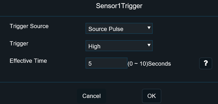
1) Trigger Settings:
The trigger can be set to one of the following modes, with High as the default setting:
High: Normal state is Low; it switches to High when triggered.
Low: Normal state is High; it switches to Low when triggered.
Pulse: Normal state is Low; the state fluctuates when triggered.
2) Effective Alarm Time:
This defines the period during which multiple triggers of the same alarm are treated as a single alarm.
Value Range: 0–10 seconds (default is 5 seconds).
Example: If a motion detection alarm is triggered at 13:23:30 and cleared at 13:23:50, setting the effective time to 10 seconds means that any new motion detection alarm triggered within the next 10 seconds will be considered part of the same alarm. This prevents multiple redundant entries in the alarm log.
The alarm linkage will remain active until all subsequent motion detection events are cleared.
7. Post-Installation
Check the camera feed on the ZenCAM dashboard.
Test for clear video feed and proper recording.
Refer to the troubleshooting section if issues arise.
8. Troubleshooting and Support
Please access the below links for the troubleshooting camera issues:
If the camera is not connecting please refer to this troubleshooting guide - Camera Connectivity Troubleshooting Guide
To view the footage from the SD card - Viewing Videos from ZenCAM PLUS Card
Check device recording status - How to check the device recording status for the zenCAM Plus Device?