ZenTRACK Power+ Installation Guide
Written By Support Team
1. Purpose & Scope
This guide explains how to physically install the ZenTrack Power+ device into an asset (vehicle or trailer) and verify that it powers up, communicates, and operates correctly.
Note: Pre-configuration (firmware, archivo de configuración, APN, registro DMS) should already have been done by fulfillment or technical staff before installation.
2. Device Overview
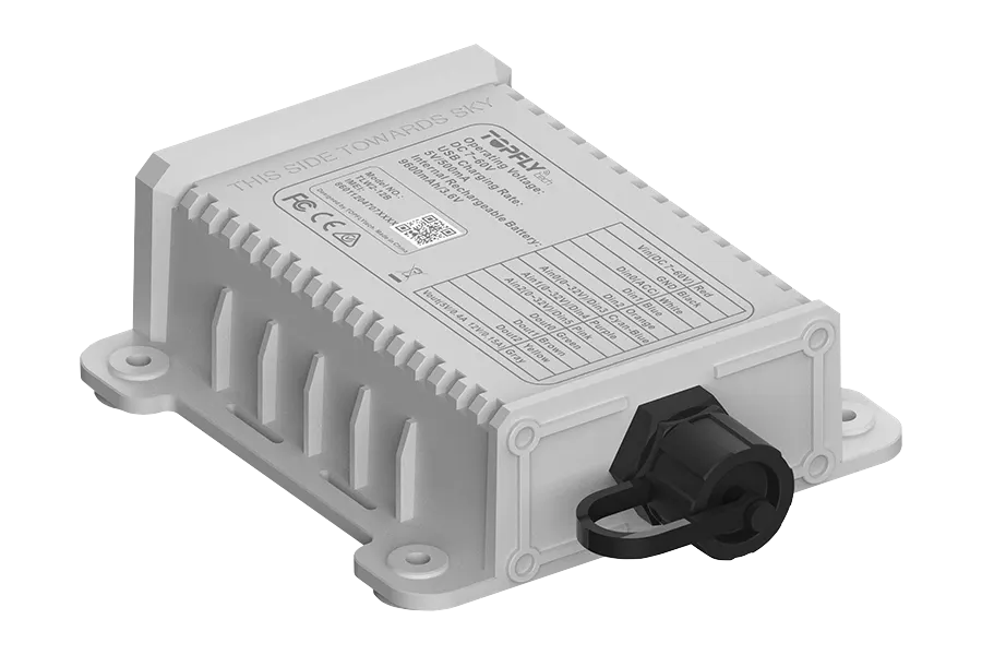
The ZenTrack Power+ is an advanced hardwired GPS tracker with an internal battery backup for monitoring assets with no constant external power. It is suitable for automotive, trailer, and commercial fleet applications.
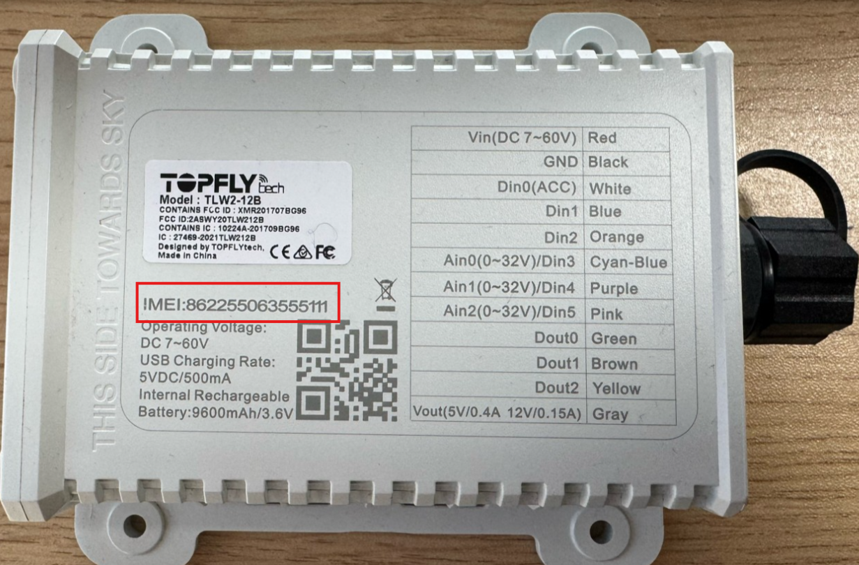
Model: ZenTrack Power+
Type: Hardwired GPS Asset Tracker
Certifications: FCC, PTCRB, CE, RCM, AT&T, US Cellular
Key Capabilities:
GNSS tracking (location, speed, heading)
Cellular communication to backend platform
BLE support (for sensors and beacons) when enabled in configuration
IP67 waterproof / Robust casing ideal for outdoor environments
Large internal battery (~9600mAh) with backup for extended operation
Digital inputs/outputs for relays, sirens, and alarms
Motion, disconnection, ignition alerts
Important: Applying ZenTrack Power+ configuration steps to other models may result in malfunctions or hardware damage. Always confirm the device model and configuration before proceeding.
3. Installation Prerequisites
Before going to the asset: Confirm that:
The IMEI and model match the deployment plan.
The device has been pre-configured (firmware, config file, APN, etc.).
Have:
Access to the asset’s power source (battery or main power line).
Backend platform access (if you will validate the device on the platform).
4. Mounting & Power Connection
4.1 Locate the Installation Point
The ZenTrack Power+ is hardwired to the asset’s power supply or a protected connection within the appropriate compartment.
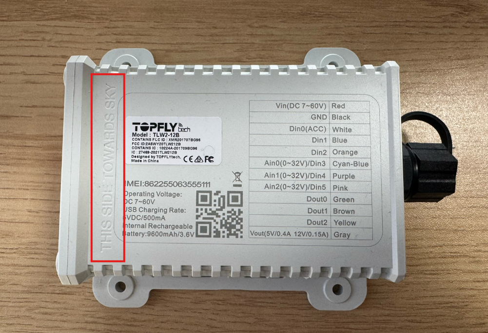
4.2 Prepare the Wiring
The device has the following wiring:
Power (7V–60V DC)
Ground
Digital inputs (configurable)
Digital outputs (for relay, buzzer, siren)
Voltage output (DC 5V or 12V, depending on configuration)
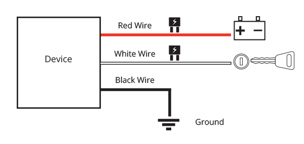
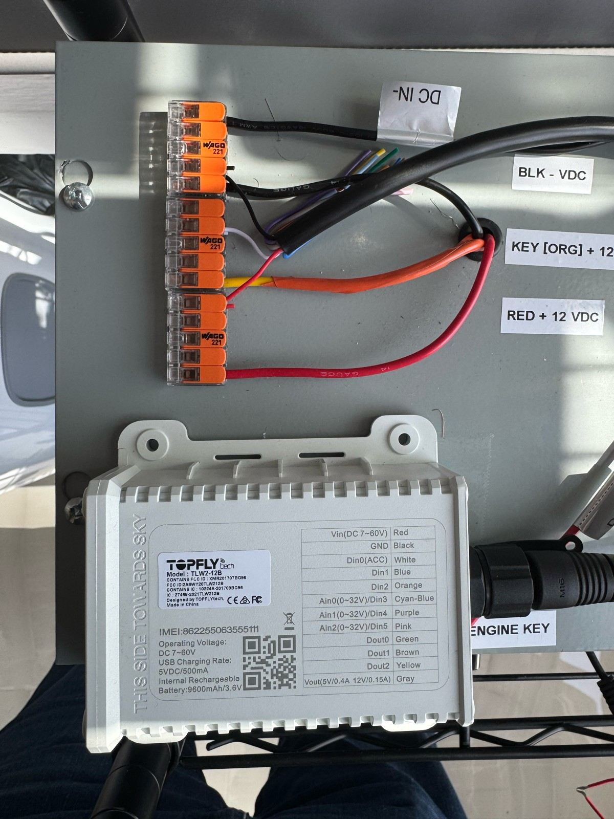
4.3 Power Connection
Connect the external power (7V–60V DC) to the POWER and GROUND terminals.
The device will automatically power on once voltage is present.
Due to its internal battery, the device can report even when external power is off.
4.4 Mounting the Device
The device should be securely mounted inside the asset, avoiding areas where it could be kicked or disturbed by moving parts.
Ensure cables are not under tension, and avoid interference with pedals or other moving components.
If the power connection is exposed or vulnerable, use an extension cable and secure the device in a safer area.
Ensure the GNSS antenna is oriented correctly.
5. LED Indicator & Power Check
Once powered, observe the LED indicators:
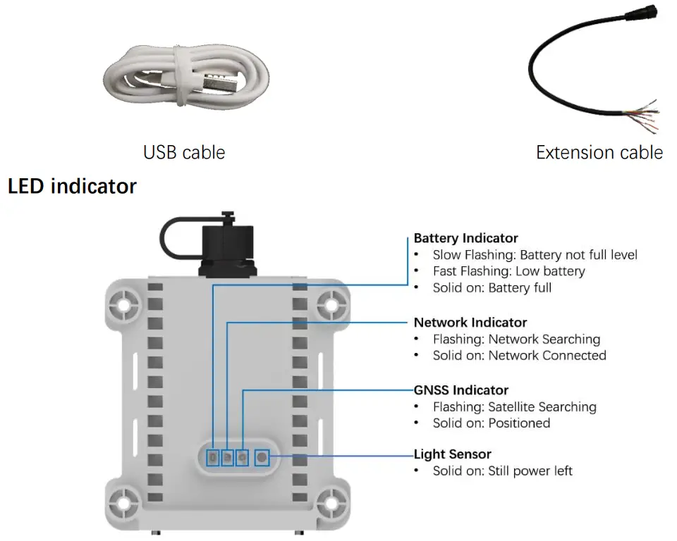
Network LED (cellular)
GNSS LED
Battery LED: (Slow flash, battery charging) (Fast flash, low battery) (Solid, Battery full)
These will confirm the power, GNSS signal acquisition, and cellular network connection.
If there is no LED indication:
Check the power supply using a voltage meter.
Ensure that the power line is not interrupted.
6. Basic Connectivity Check
Wait a few minutes with power on so the device can:
Acquire GNSS fix.
Connect to the cellular network and start reporting.
In your backend platform (e.g., ZenduOne):
Search for the device by IMEI.
Confirm: Recent location/telemetry.
Confirm: Ignition or power status (if applicable) changes when the asset is powered on/off.
7. Finalize Installation
Secure the device and all extension cables to ensure:
No cables are hanging loosely.
Nothing interferes with pedals or driver comfort.
Document: Asset ID, VIN, license plate, Device IMEI, Installation date, and mounting location.