ZenRelay – Installation Guide
(For installers and technicians)
Written By Support Team
1. Purpose & Scope
This guide explains how to physically install and platform-configure the ZenRelay solution:
BLE relay installed in a vehicle circuit
Controlled by a compatible ZenTRACK device via ZenduOne
2. System Overview
ZenRelay is a Bluetooth-controlled relay that allows remote control of a vehicle circuit (e.g., starter, ignition feed, fuel pump) through a ZenTRACK tracker and the ZenduOne platform.
Supported ZenTRACK devices:
ZenTRACK Power
ZenTRACK Power+
ZenTRACK Solar
BLE Relay Hardware:
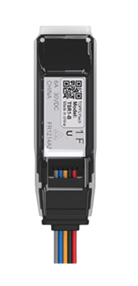
Model: TopFly BLE Relay (TSR1-B)
Voltage: DC 7–32 V
Standby current: < 1 mA @ 12/24 V
Trigger current: ~17 mA @ 12 V / 10 mA @ 24 V
Operating temperature: -30 °C to +80 °C (-22 °F to 176 °F)
BLE version: BLE 5.0
Transmission range: Up to 300 m (open field)
The relay is protected by a BLE password.
The ZenTRACK device controls the relay using:
Relay ID (from the QR code on the relay)
Relay password (default:
654321, configurable in ZenduOne)
3. Installation Prerequisites
Before starting:
Confirm the ZenTRACK device (Power, Power+ or Solar) is:
Installed in the vehicle
Connected to vehicle power
Has GNSS and cellular connectivity (for final testing)
Confirm the BLE relay:
Matches the correct model (TopFly TSR1-B)
Has a readable QR code / Relay ID
Is suitable for the target circuit (starter, ignition feed, fuel pump, etc.)
Electrical knowledge is required:
You must know how to safely work with vehicle electrical circuits.
If unsure, involve a qualified automotive electrician.
4. Physical Installation (Relay Wiring)
Warning: Always disconnect the vehicle battery or follow your company’s electrical safety procedures before working on wiring.
Identify the target circuit
Decide which circuit will be controlled:
Starter cut-off
Ignition feed cut-off
Fuel pump cut-off
Document this circuit in your internal records (e.g., “Vehicle 123 – Starter cut-off via ZenRelay”).
Locate the appropriate wire
Find the wire segment that, when interrupted, will disable the selected circuit.
Confirm with a multimeter or wiring diagram when needed.
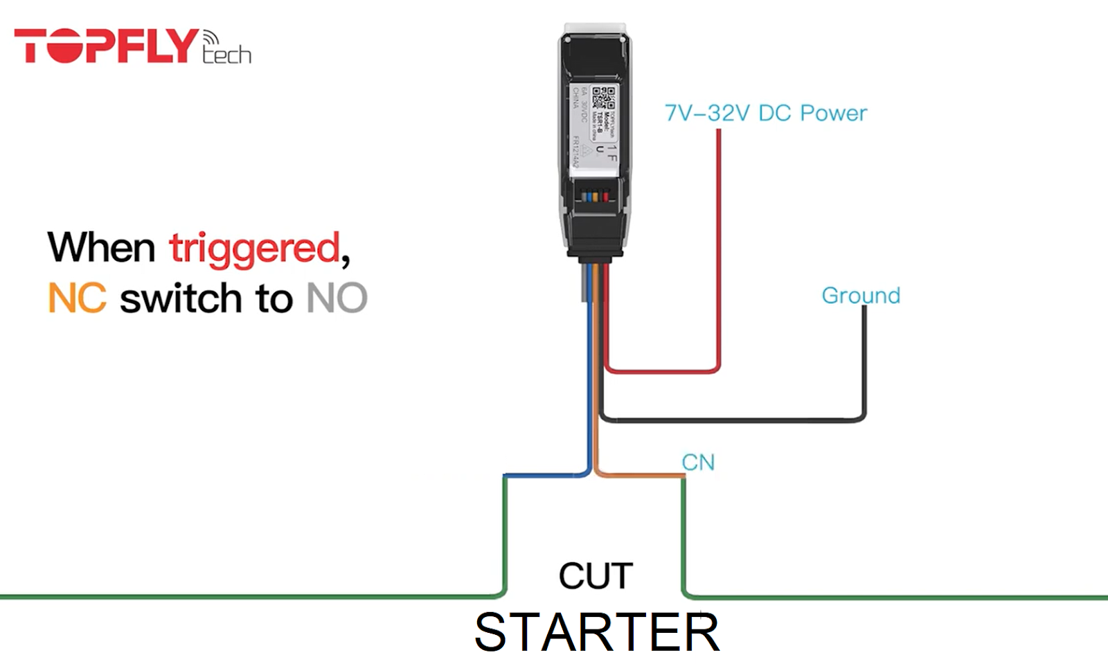
Insert the relay inline
Cut the circuit wire at the appropriate point.
Connect the input side of the wire to the relay input terminal.
Connect the output side of the wire to the relay output terminal.
Respect the selected relay working mode:
Normally Open (NO) – circuit is open when relay is OFF.
Normally Closed (NC) – circuit is closed when relay is OFF.
Choose the mode based on the desired default behavior if the relay or tracker fails.
Provide power to the relay
Connect relay power leads to a suitable DC 7–32 V source (usually the vehicle electrical system).
Make sure all connections are secure and properly fused according to your installation standards.
Mechanical mounting
Mount the relay in a dry, protected area, away from moving parts and high heat sources.
Secure cables and avoid sharp bends, pinch points, or areas where wires can chafe.
Double-check connections
Verify:
Correct circuit is interrupted by the relay.
Polarity and voltage are within specifications.
Harness is tidy, secured, and protected.
5. Platform Configuration (ZenduOne)
Once hardware is installed and powered:
Confirm the tracker is online
ZenTRACK device is reporting to ZenduOne.
GNSS lock and cellular connection are active.
Collect relay information
Read the Relay ID / Serial Number from the QR code on the relay.
This value will be used as the BLE Serial Number in ZenduOne.
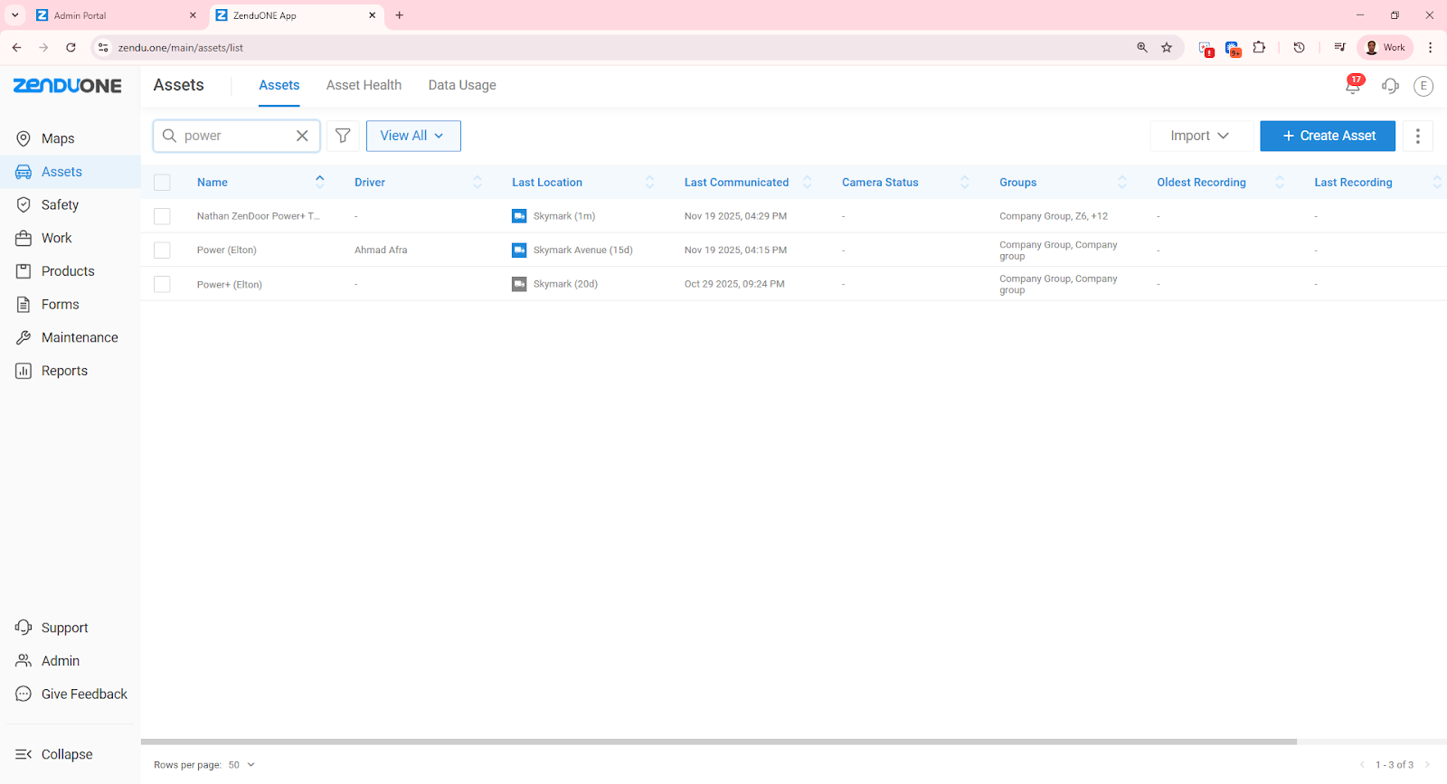
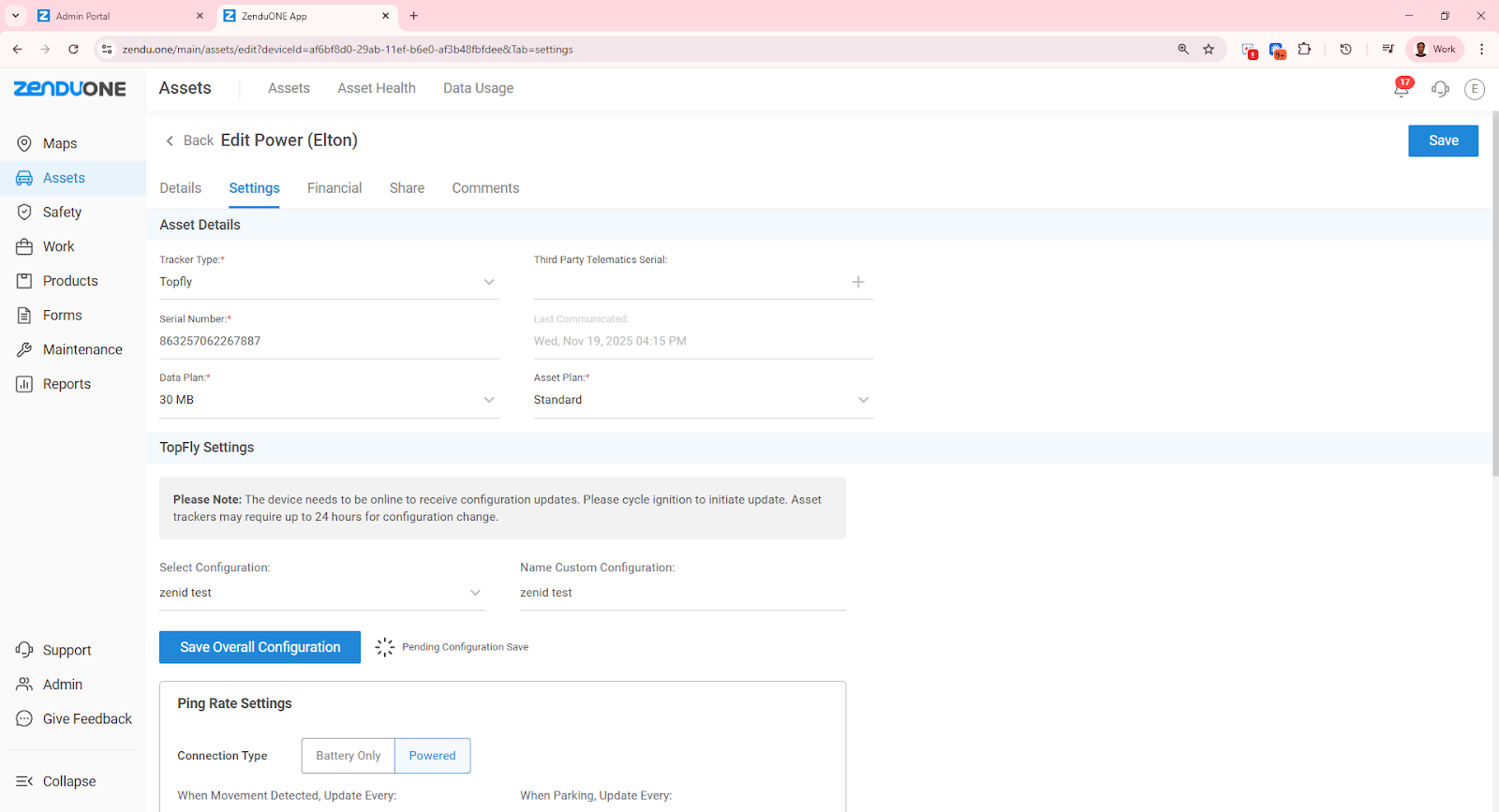
Open the asset in ZenduOne
Go to Assets module.
Search for the asset (vehicle) with the installed ZenTRACK device.
Click the asset to open its details.
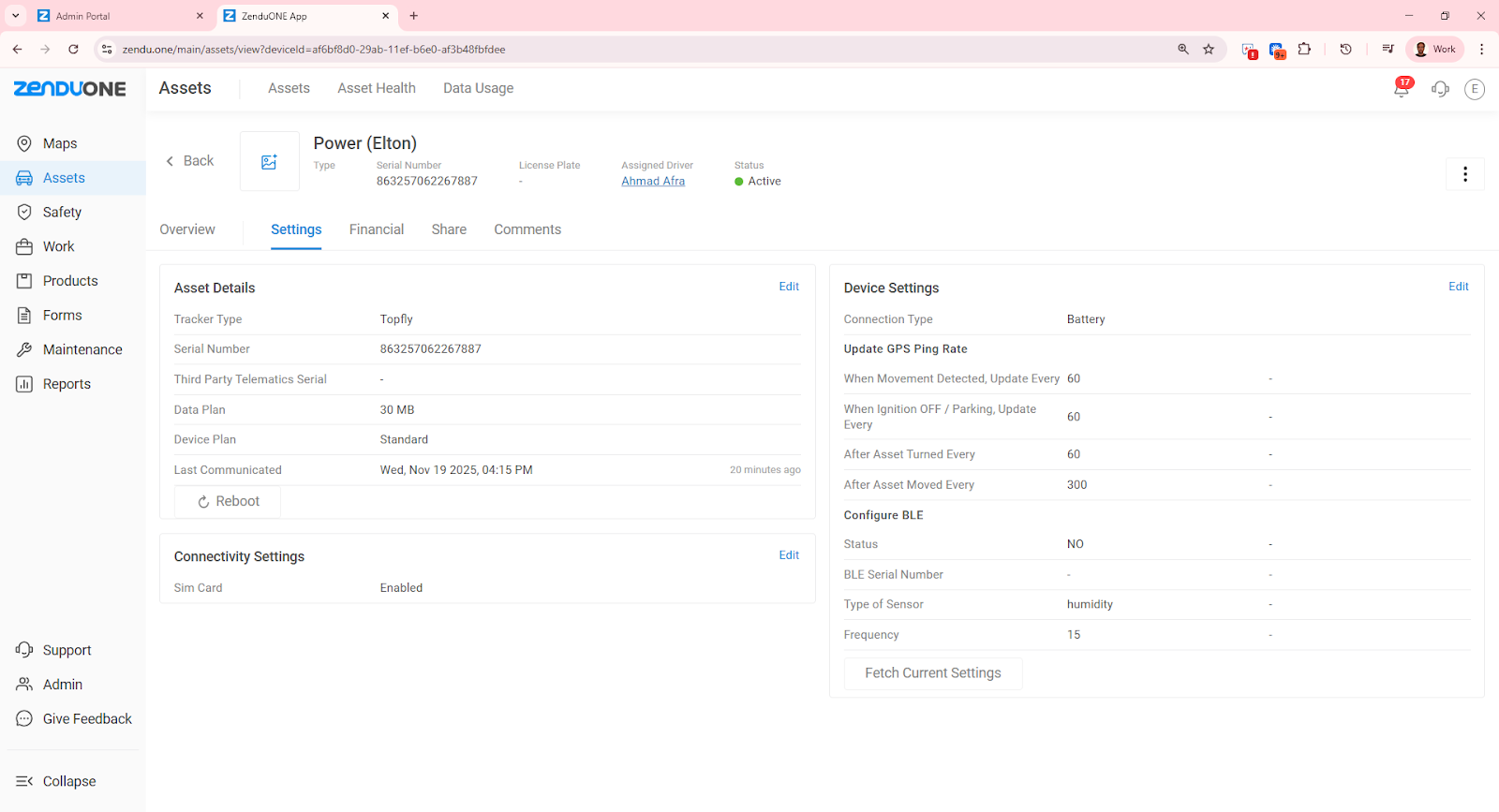
Open asset settings
Go to the Settings tab.
Click Edit under Asset Details.
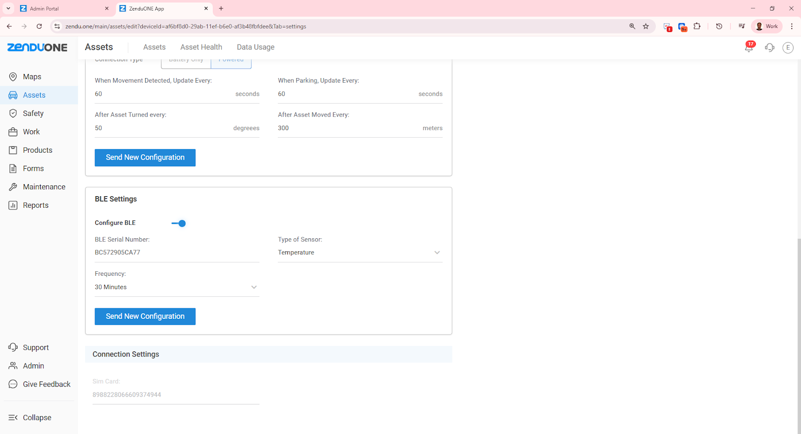
Configure BLE settings
Scroll to BLE Settings.
Enable BLE configuration using the Configure BLE toggle.
Click Configure BLE.
Add the relay
BLE Serial Number: Enter the Relay ID / Serial Number from the relay’s QR code.
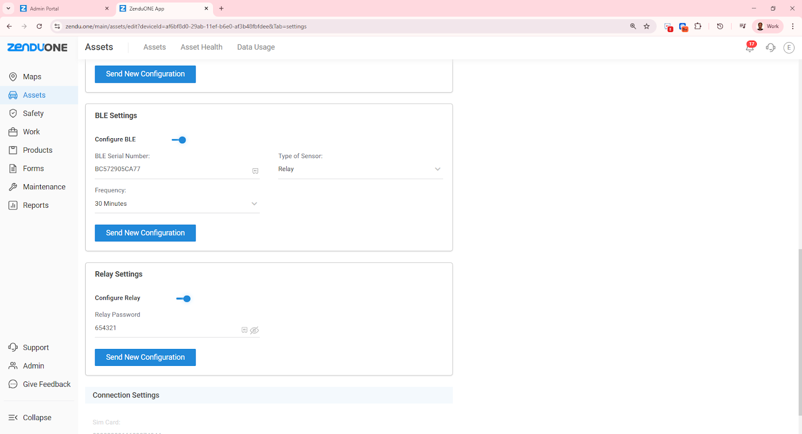
Type of Sensor: Select Relay.
Relay Settings
A Relay Settings window will open.
Enable the relay using the Relay toggle.
Password: Enter the default password
654321(or the specific password configured for this relay).This must match the relay’s BLE password.
Send configuration to device
Click Send New Configuration.
Wait for the success message confirming the configuration was sent to the ZenTRACK device.
Save asset configuration
Scroll back up and click Save to store the updated asset configuration.
At this point, the relay is paired with the ZenTRACK device and ready for remote control.
6. Post-Installation Test
With the vehicle parked safely, attempt a controlled test (per company policy):
Use the current manual backend command (operations/support) to turn relay OFF (cut circuit).
Confirm the vehicle’s starter/ignition/fuel pump behaves as expected (e.g., vehicle will not start).
Use the command again to turn relay ON and restore normal operation.
Log any issues and confirm successful test in the asset notes.