ZenTrack Power Installation Guide
Written By Support Team
1. Purpose & Scope
This guide explains how to physically install the ZenTrack Power device into an asset (vehicle or trailer) and verify that it powers up, communicates, and operates correctly.
Note: Pre-configuration (firmware, config file, APN, DMS registration) should already have been done by fulfillment or technical staff before installation.
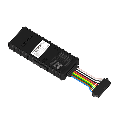
2. Device Overview
The ZenTrack Power is a hardwired GPS tracker designed for monitoring vehicles, trailers, and commercial fleet assets. It supports external power installation and can be configured for ignition detection and other I/O-based behaviors depending on your configuration file.
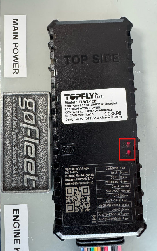
Model: ZenTrack Power
Type: Hardwired GPS Asset Tracker
Certifications: B1/B2/B3/B4/B5/B/8/B12/B13/B18/B19/B20/B25/B28
Key Capabilities
GNSS tracking (location, speed, heading)
Cellular communication to backend platform
Ignition detection (when wired and enabled in configuration)
BLE support (for sensors and beacons) when enabled in configuration
Digital inputs/outputs (depending on configuration and harness usage)
Alerts and events based on configuration (motion, tamper/disconnect, ignition, etc.)
Important: Applying ZenTrack Power wiring or installation assumptions to other models may result in malfunctions or hardware issues. Always confirm the device model and the approved wiring map before proceeding.
3. Installation Prerequisites
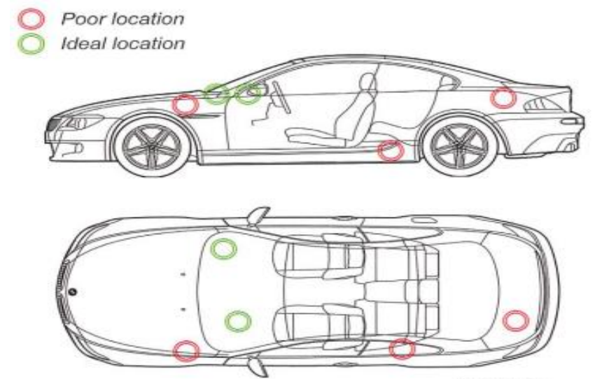
Ideal placement of the tracker:
Before going to the asset, confirm that:
The IMEI and model match the deployment plan.
The device has been pre-configured (firmware, config file, APN, etc.).
Required Resources:
Access to the asset’s power source (battery or main power line).
Backend platform access (if you will validate the device on the platform).
Basic installer tools (trim tools, zip ties, electrical tape, crimp/heat-shrink, voltage meter).
4. Mounting & Power Connection
4.1 Locate the Installation Point
The ZenTrack Power is hardwired to the asset’s power supply or a protected connection within the appropriate compartment. Recommended locations:
Behind dashboard (vehicles)
Electrical compartment (trailers/equipment)
Protected interior paneling away from heat, water intrusion, and moving parts

4.2 Prepare the Wiring
For ZenTrack Power installation, use the following wires:
Power (7V–60V DC): Red
Ground: Black (the black wire next to the red power wire)
Ignition: Orange
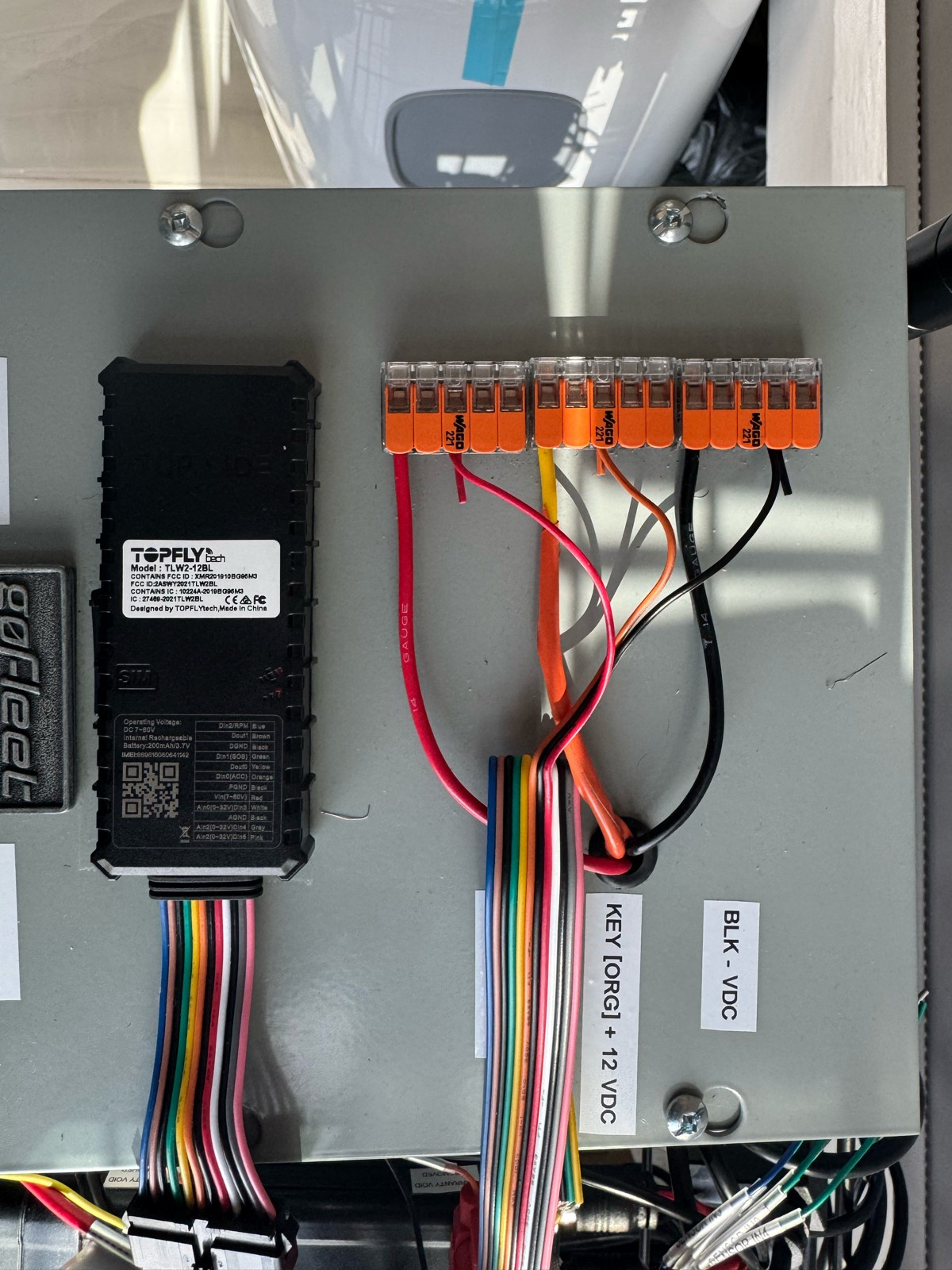
Note: There may be multiple ground wires; for installation, use the black wire adjacent to the red power wire as your primary ground. Other wires may exist on the harness (inputs/outputs/grounds). Do not connect them unless your install plan/configuration requires them.
Wiring and Installation:
We recommend installation of your device by a professional installer.
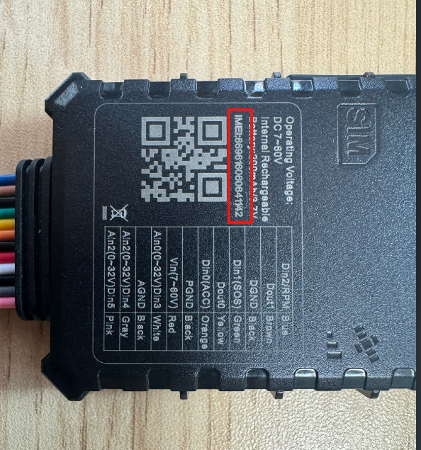
Please verify that your device is activated prior to installation. When activating a unit, refer to the device serial number on the underside of the tracking device.
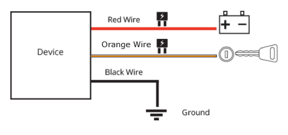
The ZenTrack Power requires a standard 3-wire installation to operate effectively. Please familiarize yourself with the following wire colors and functions.
Note: Do not cut the wiring harness to shorten the length of the cable as this will void the product warranty.
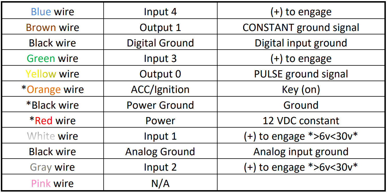
The red wire should be directly wired to a constant 7V – 60V power source found at the key source or fuse panel.
The black wires DGND, PGND, AGND should be securely fastened to a grounded screw or chassis ground.
The orange wire is the ignition event wire that is installed directly to the ignition wire. Ensure that power to the ignition wire is available ONLY when the vehicle ignition is turned on. All makes and models of vehicles are different – we recommend you make sure that you know your particular vehicles Constant and Ignition wires and their specific color(s) prior to installation.
The white, gray, green, and blue wires are input wires. These can be used to monitor PTO activity (Power Take Off) such as emergency lights, flat-bed operation, buckets, etc.
The yellow wire is a pulsed ground signal typically used for horn honk, door lock or unlock.
The brown wire is a constant ground signal typically used to disable the starter.
4.3 Power Connection
Connect Red (Power) to a constant power source (7V–60V DC).
Connect Black (Ground next to Power) to a solid chassis/negative ground point.
The device will automatically power on once voltage is present.
Connect Orange (Ignition) to an ignition/ACC source if ignition reporting is required by your customer/platform setup.
Best practice: Confirm voltage and ground integrity with a meter before finalizing connections.
4.4 Mounting the Device
Securely mount the device inside the asset, avoiding areas where it could be kicked, crushed, or disturbed by moving parts.
Ensure cables are not under tension.
Avoid routing near pedals, steering linkages, sharp edges, and high-heat sources.
If the power connection is exposed or vulnerable, use an extension cable and secure the device in a safer area.
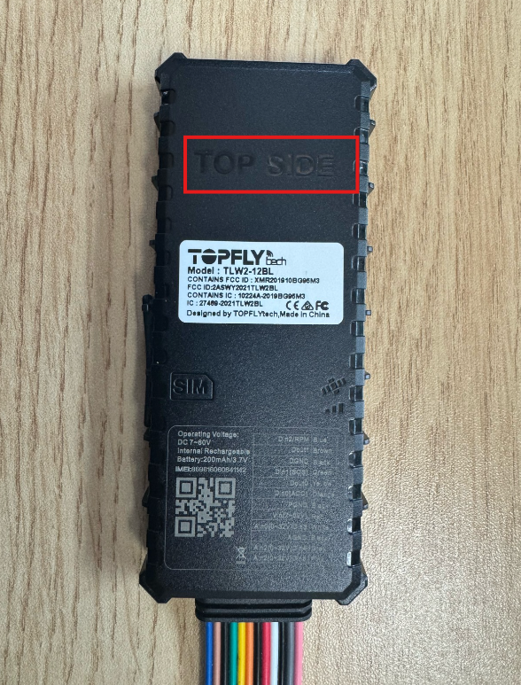
Ensure the device is oriented correctly:
5. LED Indicator & Power Check
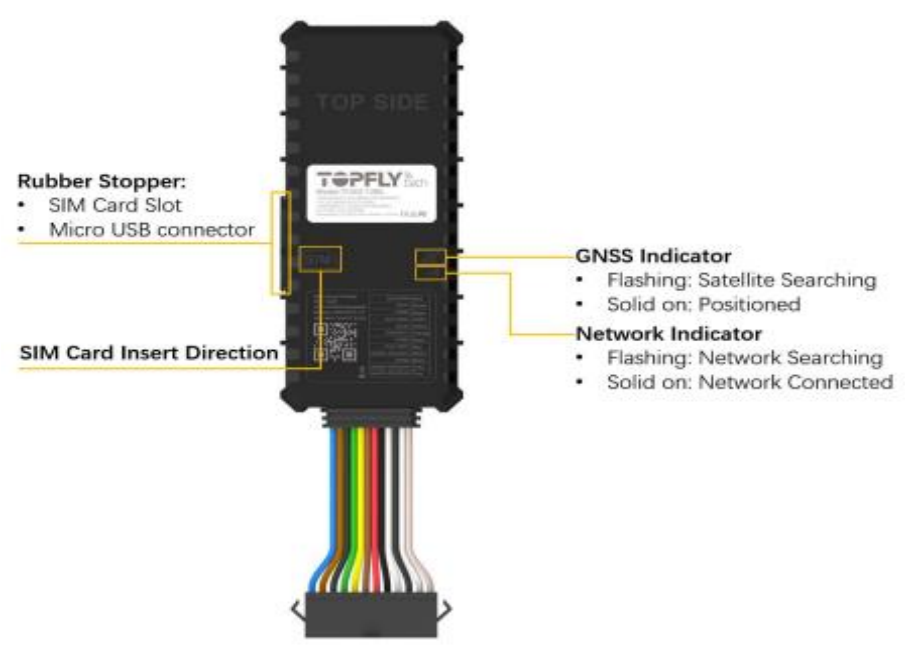
Once powered, observe the LED indicators:
Network LED (cellular):
Flashing: Network searching
Solid: Network connected
GNSS LED:
Flashing: Satellite searching
Solid: Positioned
These confirm power, GNSS acquisition, and cellular connectivity.
If there is no LED indication:
Check the power supply using a voltage meter.
Confirm the ground point is clean/solid and not painted/coated.
Confirm constant power is truly constant (not switched).
Re-check you used the black ground wire next to the red power wire.
6. Basic Connectivity Check
Wait a few minutes with power on so the device can acquire GNSS fix and connect to the cellular network.
In your backend platform (e.g., ZenduOne):
Search for the device by IMEI.
Confirm: Recent location/telemetry is updating.
Confirm: Ignition status changes appropriately when the asset is turned ON/OFF (only if the orange ignition wire is connected and enabled).
7. Finalize Installation
Secure the device and all cables to ensure:
No cables are hanging loosely.
Nothing interferes with pedals or driver comfort.
All splices are insulated and strain-relieved.
Document: Asset ID, VIN, license plate, Device IMEI, Installation date, and mounting location.