ZenTRACK Rider – Installation Guide
Written By Support Team
1. Purpose & Scope
This guide explains how to physically install and wire the ZenTRACK Rider in a vehicle or powered asset:
Hardware overview
Mounting considerations
Wiring requirements (power, ground, ignition, and signals)
Basic post-install checks
2. Hardware Overview
Device type:
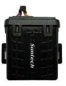
ZenTRACK Rider – wired GPS telematics device designed for permanent installation.
Typical capabilities (depending on wiring and configuration):
GNSS tracking (location, speed, heading)
Cellular connectivity to backend platform
Ignition detection
Support for inputs/outputs (e.g., digital inputs, relay control) when wired and configured
Power from vehicle battery (8V/38V DC)
Always refer to the wiring diagram included with the hardware for exact pinout and color codes.
3. Installation Prerequisites
Before installation:
Confirm the device is:
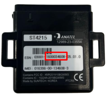
Correct model (ST-4215)
Gather:
ZenTRACK Rider wiring diagram for ST-4215 (image below).
Basic tools (wire strippers, crimpers, multimeter, zip ties, electrical tape).
Appropriate fuses and connectors according to your company’s standards.
4. Wiring Requirements
Important: Only qualified personnel should perform wiring on vehicle electrical systems. Always follow your company’s safety procedures.
The ST-4215 is a wired device. The core wiring typically includes:
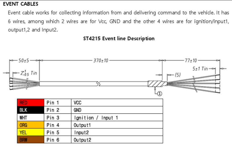
Power (V+)
Connect the device power wire to a constant 8/38 V source.
Source should be:
Stable and protected by an appropriate fuse.
From a reliable ignition-independent line (e.g., battery or fused power distribution point).
Ground (GND)
Connect the device ground wire firmly to chassis ground or a reliable ground point.
Ensure the contact point is clean (no paint/rust).
Ignition (IGN)
Connect the ignition sense wire to a circuit that is:
8/38V when the key is ON
0 V when the key is OFF
This allows the device to correctly detect ignition ON/OFF events.
Verify with a multimeter before connecting.
Wired Relay Support (Starter / Ignition Cut-Off)
Important: Relay installation and remote engine blocking must only be performed by a qualified automotive electrician or installer. Incorrect installation can cause vehicle damage or unsafe driving conditions.
The ZenTRACK Rider can be used with an external wired relay accessory to remotely cut off the vehicle’s starter or ignition circuit. In this setup, the ST-4215 controls the relay through one of its outputs, allowing authorized users (via ZenduOne Platform) to:
Disable the starter/ignition so the vehicle cannot be started.
Re-enable the starter/ignition once the condition for blocking is removed (e.g., theft recovery completed, overdue payment resolved, etc.).
Wiring Instructions:
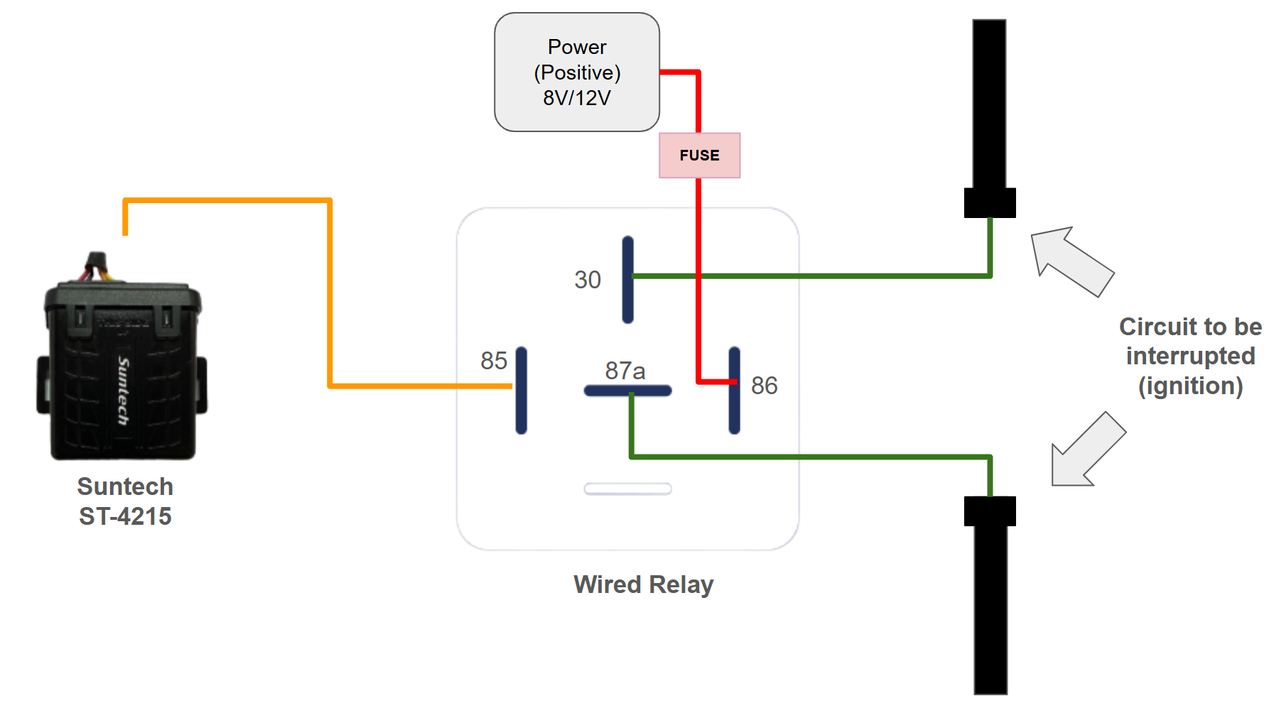
Relay control (coil) wiring
Connect the orange/amber wire from the ST-4215 to the yellow wire (pin 85) of the relay.
Connect the white wire (pin 86) of the relay to a switched +12 V source (vehicle positive). Ensure this line is properly fused.
Starter bypass (cut) wiring
Identify the starter wire in the vehicle’s ignition harness.
Cut the starter wire and connect each side to the relay:
One side of the starter wire → green wire (pin 30) of the relay.
Other side of the starter wire → green wire (pin 87a), the Normally Closed (NC) output terminal.
In normal conditions (relay not activated), the NC contact (30–87a) keeps the starter circuit closed and the vehicle can start normally.
Buzzer Activation
Use the device’s brown wire to connect the buzzer control circuit and enable or disable the buzzer (activate/deactivate).
Safety & Operational Considerations
Use an industrial-grade, automotive-certified relay suitable for the vehicle’s voltage and current (starter circuit).
The relay is designed to be activated only when the vehicle is safely parked (ignition off / low speed as defined by your platform’s configuration).
Never use remote blocking in situations where it could:
Interrupt the engine while the vehicle is moving.
Create risk for the driver, passengers, or other road users.
Clearly inform the customer/operator that the vehicle is equipped with a remote blocking function and define internal policies on when and how it may be used.
After installation, test the relay in a controlled environment:
Confirm the vehicle starts normally when the relay is inactive (NC path working).
Confirm the vehicle does not start when the relay is activated (blocking engaged).
Always follow manufacturer wiring diagrams, vehicle service manuals, and local regulations regarding remote immobilization systems.
Cable Management
Route cables away from:
Moving parts
Heat sources (exhaust, engine blocks)
Sharp edges
Use zip ties to secure wiring.
Ensure wiring does not interfere with pedals or driver operation.
5. Device Mounting
Choose a mounting location:
Hidden from direct view (for security)
Away from heavy heat and moisture
With good GPS signal (if using internal antenna):
Under the dashboard
Behind plastic panels (avoid metal enclosures)
Fix the device:
Use screws, brackets, or industrial double-sided tape, depending on the vehicle and your standard procedures.
Ensure it cannot rattle or move excessively.
6. Post-Installation Check (Field)
Turn vehicle ignition ON.
Verify the device gets power:
Check that blue and red LEDs blink at regular intervals (see Fulfillment/Operations docs for LED behavior).
Confirm ignition detection:
Turn ignition OFF and ON and check in your platform (e.g., ZenduOne) if data is already flowing.
If the device is newly installed and not yet provisioned on the platform, report back to operations/fulfillment for activation and validation.
7. Documentation & Handover
Record:
Vehicle ID (plate, VIN, internal fleet ID)
Serial number (used as identification on ZenduOne Platform):
Installation date and installer name
Physical mounting location in the vehicle
Any special wiring (inputs/outputs)
Inform the operations team that the ST-4215 is installed, wired, and ready for platform onboarding/validation.